
Products

HS742 3D Cross-Hatch Sensor

PRODUCTS: HS742

The HS742 with Blue Laser Technology is a 3D Cross-Hatch sensor and is specifically used for measuring countersink alignment, fastener depth and dielectric fill height in the aerospace industry.

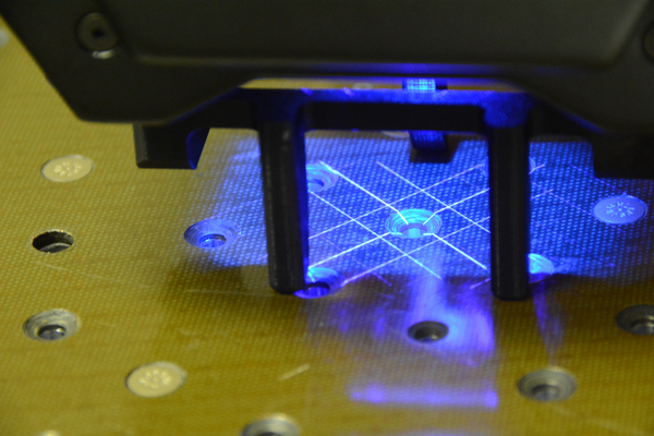
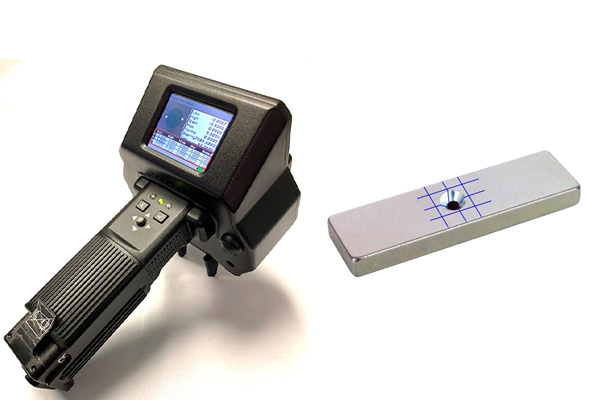
The HS742 DSP sensor with Blue Laser Technology is a 3D laser profiler housed in a totally self-contained, portable, handheld package. Expanding on the unique capabilities of the LaserGauge® line of DSP sensors, the HS742 utilizes a laser stripe grid with cutting edge optics and is specifically designed for inspecting and measuring fastener flushness, countersink alignment and dielectric fill height. Surface maps are displayed in real-time on the color LCD, and measurements are extracted and simultaneously written to the data table.

Download Product Datasheets

LEARN MORE ABOUT THE HS742 3D CROSS-HATCH LASER SENSOR

  • Features & Applications

  • Field of View & Laser Options

  • Virtual Gauges

  • Specifications

  • Accessories

FEATURES & APPLICATIONS

The HS742 is battery powered and portable

  • Field of View Options: 1.20” x 1.20” (30mm x 30mm) Scanning Region
  • Display Size: 2.4” Horizontal
  • Features include:
    • Blue cross-hatch lasers
    • 1270 scan points over sensor field-of-view
    • 1 GHz DSP processor – measurements are completed in as little as ½ second.
    • Totally self-contained – no need for external PC or cables for operation
    • Automatic gain optimization – scanning on wide variety of colors/finishes

HS742 Applications

Application Standoff
Aerospace Countersink – composite or metal, flat or curved Countersink
Aerospace Fastener – composite or metal, flat or curved Fastener
Aerospace Dielectric Fill – composite or metal, flat or curved Fastener
NOTE: The Fastener and Countersink standoff comes standard with the HS742 sensor.

BACK TO TOP

FIELD OF VIEW & LASER OPTIONS

Field of View Options

The HS742 comes in 1 field-of-view (or scan width).
FOV Option Field-of-View Scanning Grid Resolution Diameter Range Accuracy
-F20 1.20” x 1.20” (30mm x 30mm) 0.0015” (38µm) 0.250” to 0.625” (0.635mm to 15.87mm) +/- 0.001" (25µm)
  • Scanning Technology

    The HS742 Sensor model is available with 3D Cross-Hatch Scanning technology. Learn more about how LaserGauge® scanning works.

  • Blue Laser Technology

    Blue laser technology works accurately on various surfaces including painted, unpainted, translucent, transparent, some plastic, composite, and shiny.

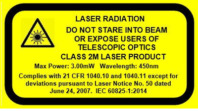
Laser Safety Warning Label

BACK TO TOP

VIRTUAL GAUGES

Virtual Gauges that come with the HS742

"Virtual Gauges" are the mathematical algorithms used to process a scan and extract measurements from it. The following Standard Virtual Gauges are provided as a part of the preloaded configuration for both the HS702 and HS703 and are used mostly for Gap/Flush and Sheet Metal applications in the automotive industry.

  • Countersink
  • Fasteners
  • Dielectric Fill

Custom Virtual Gauges can be developed/created according to customer requirements and measurement methodology upon request. Learn more about Standard and Custom Virtual Gauges.


Measurement output includes numerical and graphical displays as well as auditory feedback
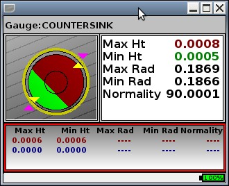
  • Display Output

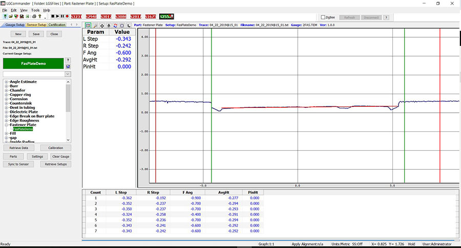
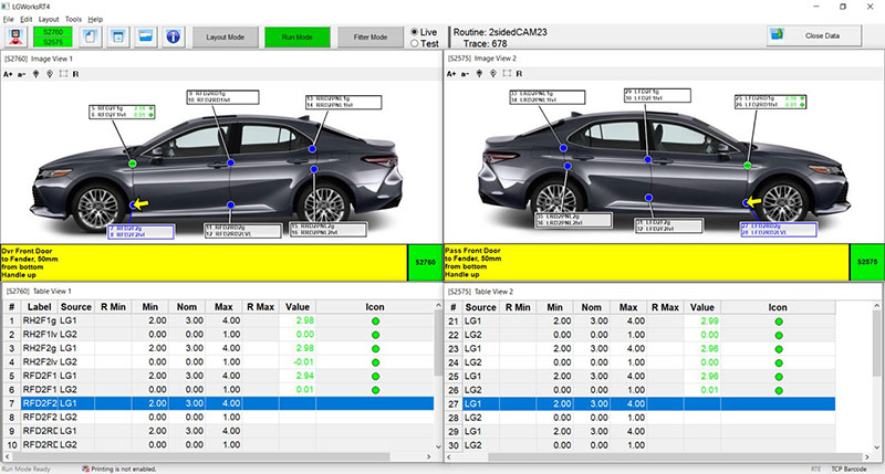
    Numerical and graphical results are displayed and can indicate in- or out-of-spec conditions. Operation feedback is provided to assist the operator in obtaining the best measurements.
  • Auditory Output

    A variable volume speaker will sound different tones to indicate in- or out-of-spec measurements, errors or misreads, and low battery.
  • Data Output

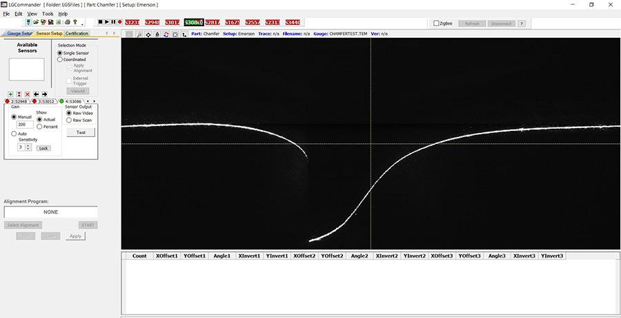
    All processed scans and the extracted measurements are automatically saved to the sensor memory for later retrieval. When the sensor is plugged into a PC it will map the data memory as a drive, much like a USB memory stick so that retrieving files is fast and easy.

BACK TO TOP

SPECIFICATIONS

HS742 Specifications

  • User Input

    2 sets of 3 LED’s, 5-Way Joystick and 2 Buttons
  • Communications

    Wireless - 2.4GHz ZigBee module with ZigBee USB Stick for computer Cable - USB 2.0A to Mini 5-Pin USB, 6’
  • Processor

    1GHz Speed
  • Memory

    8GB of data/scans/routines
  • Battery

    High capacity, rechargeable lithium-ion Inspired Energy series NB2037

  • Shock Protection

    Cast urethane housing
  • Environment

    0° - 70° C
  • Size

    5.13" (w) x 4.88" (h) x 8.56" (l)
  • Weight

    23 oz. (27 oz. with battery)
  • Display

    2.4” Color Display
  • Touchscreen

    No
  • Scan Type

    3D Cross-Hatch
  • Laser Color

    Blue
  • PC Software Interface

    LGTools, Windows™ compatible

BACK TO TOP

ACCESSORIES

HS742 3D Cross-Hatch Sensors come standard with the following:

  • Sensor
  • 1 Countersink Standoff with 3 different countersink angle blades
  • 1 Fastener/Fill standoff
  • Zigbee Wireless USB Dongle
  • Battery charger
  • Accessory software (LGTools and LGCommander) link to software pages
  • 6’ Cable – USB 2.0A to Mini 5-Pin USB
  • Hard-shell carrying case
  • 1-year warranty

  • Optional Accessories

    • Holster
    • Standoffs
  • Included Software

    • LGTools – this application sends, retrieves, and formats data from a computer to the DSP Sensor via USB cable or ZigBee.

BACK TO TOP

LGWorks

SOFTWARE: LGWorks

LGWorks is used to create multipoint inspection routines with DSP sensors and guide operators through the routines.

An inspection routine is any number of measurements made on a part or assembly at specified locations in a predetermined order or sequence. The routines guide operators through each measurement point using graphic and/or text instructions. Several characteristics or values may be measured at a single inspection point, such as gap and flush. Calculations using the measured values can be incorporated into the routine and the user can establish the format for the data stored in files on the LaserGauge®. Once a routine is developed and saved in LGWorks, it can be sent to either an LG controller, a DSP sensor, or a PC and used wirelessly with LGWorksRT.

Download Product Datasheets

FEATURES

Features of LGWorks

Organize Routines

Routines are built in a tree-view hierarchy so that points and groups of points can easily be cut, copied and pasted, or moved using drag-and-drop functionality.

More than one measurement may be needed at each inspection point, such as gap and flush. Routine commands tell the LaserGauge® what methodology to use to make the measurements and one pull of the trigger completes all of the measurements at that location.


Operator Instructions

Photos or images of the part being inspected can be copied into LGWorks, and the individual points can be marked by drawing an arrow on the image at the exact location for the measurement. The images are displayed on the graphical controllers or DSP screens with arrows advancing automatically as each measurement is taken.


Measured Points and Calculations

Formulas that use the results from measured points can be added to the routine for calculations such as A/V gaps, parallelism, max gap, range, etc.

Spec Limits

Specification limits can be entered in the routine and used by the LaserGauge® to flag out-of-spec conditions. A second set of limits, called reasonable limits, can also be entered to help filter errant measurements and identify measurements taken at the wrong location.


Test Gauges on Saved Scans

The LaserGauge® can be used to capture raw scans of surface features, such as a weld or a gap. The scan, once retrieved, can be opened in LGWorks and used to test virtual gauge settings. The selected gauge and settings are then incorporated into the routine.


Plotted Scans

Plots showing virtual gauge tests on scans can be saved as graphic images. These images can be used in reports to document the measurement methodology.

On-screen Measurements

Measurements can also be made on-screen in LGWorks using point and click tools.

Roadmap

Routines can be documented with a printable roadmap showing each measurement point on the vehicle image and user-selectable information specific to the points in a table. Measurement data from the running of a routine can be imported into the roadmap and the values color coded as in-spec or out-of-spec.

Data Files

Data files are formatted by the user and can vary by routine. The user has a choice of delimiters and the file can include information contained in the routine or found on the controller. Operator input fields and LaserGauge® generated information can also be included in the data file, such as date, time, shift, operator, VIN, feature label, description, etc.

SPECIFICATIONS

LGWorks Specifications

  • System Compatibility

    LG1102, LG1200, LG4101, LG5000, LG7000 controllers and all DSP Sensors

  • Communication to LaserGauge® from Computer

    LG1102-null modem serial cable; LG1200-USB null modem cable and Ethernet; LG4101-null modem cable and wireless RF; LGX000 and DSP sensors-USB cable or wireless ZigBee
  • Operating System

    Windows™
  • Disk Space

    64MB
  • Memory

    512 MB RAM

Learn more about the LGWorks Suite of LaserGauge® software products

Click here to learn more

LGCommander

SOFTWARE: LGCommander

The LGCommander software is a cost-effective, Windows™ 10 based tool, that when used in conjunction with the LaserGauge® USB Sensor, measures a wide range of applications.

For the handheld DSP sensors, HS702/HS703/HS761/HS763, setup information specified using LGCommander can be sent to the sensor via the USB cable, enabling the sensor to be operated in standalone mode with the established configuration. If running in standalone mode is not required, the HS702/HS703/HS761/HS763 DSP sensors may also be operated through a USB cable using LGCommander to provide enhanced graphic capabilities and automatic scan saving functions.

Since the remote RS750 and TS800 are always running using LGCommander, all setup information entered in LGCommander is immediately available for use by one remote sensor or multiple remote sensors in a coordinated configuration.

LGCommander is used to:

  • configure and test measurement algorithms (gauges) for specific parts
  • establish inspector, supervisor and administrative rights for the sensor
  • set operational preferences.

LGCommander & USB Sensors

For USB sensors, all setup information entered in LGCommander is immediately available for use to measure and examine the desired feature.

LGCommander Features

Features of LGCommander

Real Time Measurements

Constant scanning and running the algorithm in real-time while displaying current measurement results and profiles.


Automatic Gain Control

LGCommander automatically sets the gain of the usb sensor so you don't have to worry about dispariate surface colors or reflectivity.


Scans & Data Saved Automatically

Formulas that use the results from measured points can be added to the routine for calculations such as A/V gaps, parallelism, max gap, range, etc.

Multiple Sensors

LGCommander supports multiple sensor types. An alignment algorithm is applied to the simultaneous scans producing a calibrated, multi-view profile of a part. The inspection algorithm is then run against the combined profile to generate the desired measurements.


Analyze Profiles

Raw Video

The Raw Video test mode allows you to view the sensor signal and determine the optimum manual setting. The image of the laser will appear in the video box.

This image helps to analyze possible surface reflections, incorrect gain settings, positioning of the sensor and other manual settings. These are all items that can affect the success of accurate measurements.

On-Screen Measurements

For some profiles there might not be a virtual gauge that will work, or one that returns the measurements desired. An operator can manually measure a feature on any captured profile by using the on-screen distance measurement tool. The operator can simply select the first point or edge in the scan by left-clicking and dragging the cursor to the other point or edge and releasing the mouse. The x,y coordinates will be used to calculate the delta x, the delta y, and the absolute distance between the two selected points.

LGCommander Specifications

  • Operating Systems

    USB sensors are configured using the Windows 10™-based operating systems
  • Memory

    Minimum 256 MB recommended
  • Video Card

    Minimum of 1280 X 1024 px resolution required
  • USB Port USB

    2.0 for connection to USB and DSP sensors
  • Free Disk Space

    50 MB

Learn more about the LGWorks Suite
of LaserGauge® software products

Click here to learn more

LGWorksRT

SOFTWARE: LGWorksRT

The LGWorks Run-Time (RT) software is used primarily on moving assembly lines with DSP Sensors to run inspection routines wirelessly, created in LGWorks.

In most cases, LGWorksRT is used on a moving assembly line to make measurements on vehicles as they move through the inspection station. Routines can be run by one or two operators working simultaneously using multiple DSP sensors. The measurement results are displayed on a large screen mounted over the line and out-of-spec conditions are color-coded for easy identification.

LGWorksRT Features

Features of LGWorks

Barcode to Routine Capability

A routine can be launched in LGWorksRT by entering a trace that is specifically associated with the routine. The trace can be a VIN, a sequence number, or any identifier of the part or assembly being inspected. In assembly plants, the VIN or sequence number is usually on a barcode label attached to the part. Using the optional barcode reader on the sensor to read the barcode and associating a precise trace to a specific routine, that routine will automatically open in LGWorksRT in preparation for measuring.


One or Two Operators

Routines can be run by one operator or by two operators working simultaneously using the handheld DSP sensors.

A DSP sensor must be directly connected to the computer via a USB cable or through a wireless ZigBee link to run a routine with LGWorksRT. 


Communication

Whether the communications are accomplished wirelessly using the Zigbee module or through a USB cable inserted into a com port on the computer, LGWorksRT sends virtual gauge setup instructions, sensor messages, and other commands to the LaserGauge®. The LaserGauge® executes the measurement based on those commands and sends the results back to LGWorksRT so that they can be displayed and logged.

Optional Fit-Gate station

This option works in conjunction with LGWorksRT. The gap and flush, or “fit”, data is recorded and entered into the plant’s database or quality management system. Measurement results from the Fit-Gate station can also be gathered and filtered, with those results displayed on a separate monitor or LCD downstream where operators can adjust the ‘fit’ of any out of spec measurement.

LGWorksRT Specifications

LGWorks Specifications

  • System Compatibility

    All LaserGauge® controllers and DSP handheld sensors

  • Communication to LaserGauge® from Computer

    Zigbee USB Wireless stick or USB cable
  • Operating System

    Windows 10™
  • Disk Space

    64MB
  • Memory

    512 MB RAM

Learn more about the LGWorks Suite of LaserGauge® software products

Click here to learn more

Utilities & Software Add Ons

SOFTWARE: Utilities & Software Add Ons

The following utilities and software add-ons are available to extend the capabilities of LaserGauge® Sensors

LaserGauge® Tools Software

  • LGTools is used to retrieve files from and send files to the LaserGauge® controllers
  • LGUtility is a specialized application used to send firmware files to the controller and to retrieve firmware and operating files from the controller
  • LGImage is a graphic viewer used to view and save images and scans retrieved from the controller

LGConfig

  • Use a PC to configure all of the menu-based settings on a DSP sensor
  • Retrieve DSP sensor settings and store as a local file on a PC
  • Push the retrieved settings, or settings configured with the LGConfig user interface, to another DSP sensor to replicate all settings between sensors

LGViewer

  • LGViewer is a feature rich graphic viewer that allows panning and zooming of the scan, as well as onscreen measurement capability