About Virtual Gauges
TECHNOLOGY: About Virtual Gauges
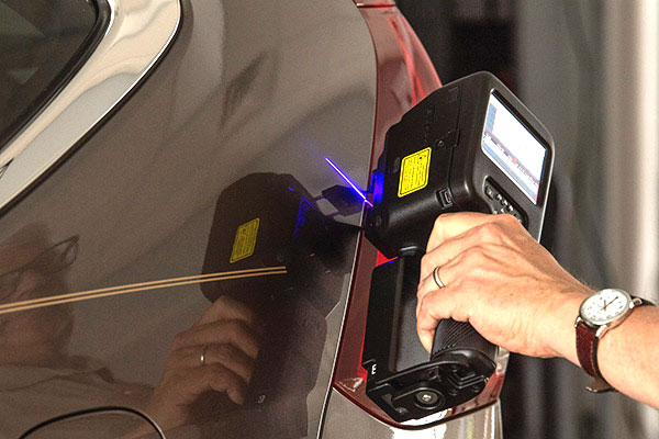
How LaserGauge® Technology Yields Accurate Measurements with Virtual Gauges
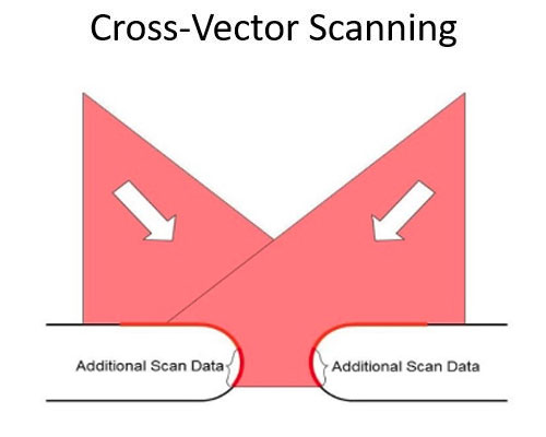
While the wide variety of laser line imaging methods provides flexibility on how scan data is obtained, the scans are meaningless unless useful measurements can be made from them. This is where the Virtual Gauges come into play. The LaserGauge® technology provides two different ways for users to configure measurements.
Standard Virtual Gauges
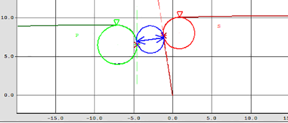
The LaserGauge® comes standard with a set of built-in Virtual Gauges that are used mostly for Gap/Flush and Sheet Metal applications in the automotive industry. Each Virtual Gauge utilizes several configuration parameters to affect the calculation method of the gauge.

Custom Virtual Gauges
Custom Virtual Gauges are developed/created according to customer requirements and measurement methodology. LaserGauge® creates custom Virtual Gauges using the LGBasic program. An LGBasic program describes the procedural steps for extracting features and/or measurements from the profile sample, logging and displaying the data, and controlling external devices, either through digital I/O and/or serial I/O. Written using either a standard text editor or LGBasicStudio, the powerful LGBasic programs can identify the most complex features and extract measurements based on the most stringent requirements. All LaserGauge® sensors come preloaded with a set of Virtual Gauges.
-
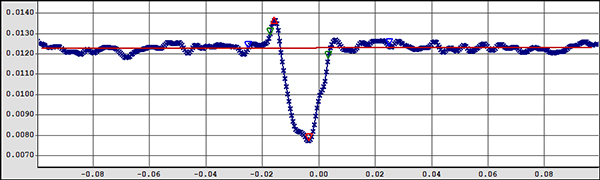
Scratch Gauge
-
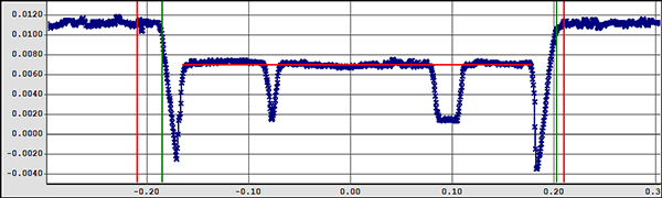
Fastner Gauge