Aerospace
APPLICATIONS: Aerospace
LaserGauge® is used for a variety of applications in aerospace assembly, repair and servicing.
Our lightweight, fast, accurate sensors coupled with leading edge technology is perfectly suited for taking accurate measurements on a wide range of flat or curved surfaces such as glossy painted or dull green primed, stainless steel, anodized titanium, highly polished aluminum, composite and many others.
AEROSPACE APPLICATIONS &
RECOMMENDED LASERGAUGE® SENSORS
-
Gap, Step,
& Angle -
Scratches, Gouges,
& Dents -
Fastener Height, Pin Protrusion, Dielectric Fill
-
Leading Edge Profile
(Bench Top & Handheld) -
Welds
-
Pitting
& Corrosion -
Radius, Break Edge,
Chamfers -
Surface Roughness/
Wrinkles
Gap, Step, & Angle
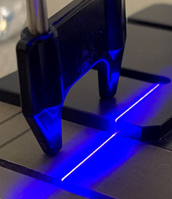

There are few options for measuring step heights between separated, nominally plane-parallel surface regions of a precision-engineered part. Obstacles to overcome are surface textures as well as accurately representing two surface profiles. Using a mechanical device will show the height of the surface may increase significantly with the tip radius in a manner that biases step height measurements on uneven surfaces.
The LaserGauge® Step algorithm automatically measures the step height between two surfaces and the peaking angle between the surfaces. The determining factor becomes other uses for the sensor and field of view requirements. All sensors come with standoffs for Gap/Flush. The TS800 comes with the proper straddle standoff but is a separate accessory for the HS702 or HS703 for measuring step.
Download Application Datasheet
Recommended Sensors
-
HS702 OR HS703 DSP SENSORS WITH RED OR BLUE LASER SINGLE STRIPE TECHNOLOGY
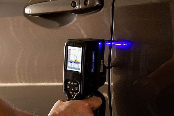
This is a handheld, untethered sensor. Most widely used for exterior painted and unpainted body panels. A separate straddle standoff accessory must be purchased for this option. -
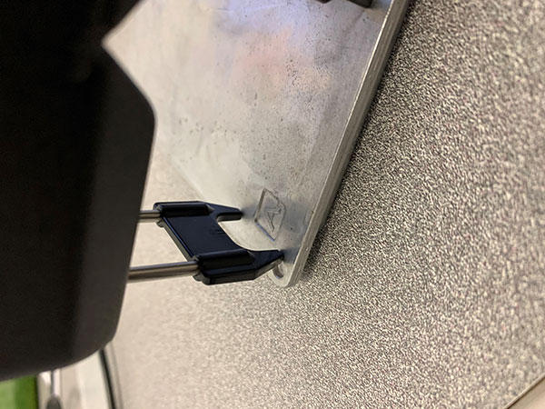
TS800 USB SENSOR WITH RED OR BLUE LASER SINGLE STRIPE TECHNOLOGY
Step features are usually small and will require a smaller device with high resolution. Laser based measuring devices resolves the problem of tip radius biasing the results. SPC or tolerance limits can be specified in the measurement algorithms. A cable connects the sensor to a laptop or optional controller. -
OPTIONAL LG5000 OR LG7000 CONTROLLER
Allows the operator to view the profile of the feature of interest while taking the measurement and ensure that the sensor is focused on the correct location.

Scratches, Gouges, & Dents
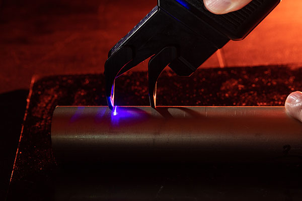
Critical components in aircraft and space vehicles can be damaged by foreign objects during repair processes or by unexpected wear during normal operation. Any material removed from a surface by a scratch or a gouge or any deformity of a surface, such as a dent, may compromise the safety of the vehicle.
Scratches and gouges on tubes, pipes and other surfaces must be measured to determine how much material has been removed, and thus, how much of the original surface or wall is remaining. Depth micrometers and other mechanical devices cannot provide meaningful measurements because of the contour of the surfaces and the small features that have to be measured. The depth and width of any visible wear or gouge must be measured to determine if the part is still qualified for flight. Thresholds for the amount of material that can be missing are in the thousandths of an inch, so the measurement instrument must achieve this resolution.
-
Download Application Datasheet
-
Download Product How-To Guides
Recommended Sensors
-
TS800 USB Sensor
The size of the feature being measured will determine the sensor field-of-view needed. For very small gouges and dents, the TS800 sensor with a 0.50" field-of-view will provide the greatest resolution. A dent or larger gouge may require a TS800 sensor with a FOV of 1.0", or 2.0", depending on the size of the feature and the resolution required. An LG5000 controller or a larger screen LG7000 can be used with the TS800 to provide the graphical feedback necessary for the operator to position the laser stripe and view the profile as the measurements are being taken. -
Optional LG5000 or LG7000 Controller
An LG5000 controller or a larger screen LG7000 can be used with the TS800 to provide the graphical feedback necessary for the operator to position the laser stripe and view the profile as the measurements are being taken.
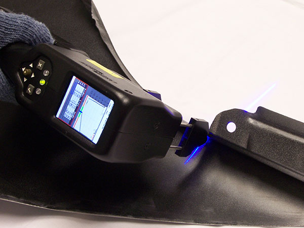
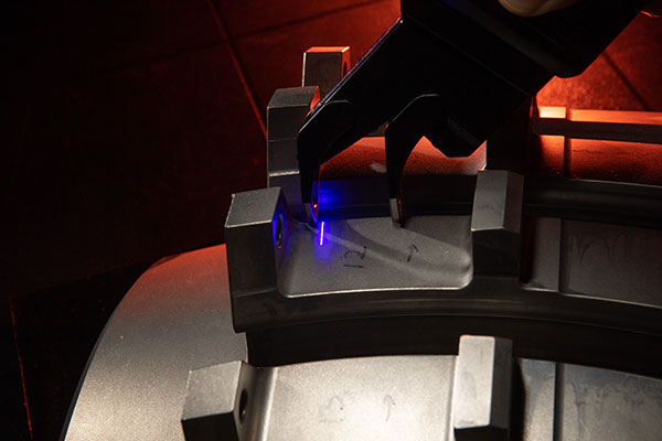
Fastener Height, Pin Protrusion, Dielectric Fill

Fasteners on the exterior of aircraft must be flush to the surface within a certain tolerance. A fastener that protrudes above or one that is driven below the adjacent surface may adversely affect performance in flight.
Mechanical devices measure the height at one single point on the fastener head and an operator must position the stylus many times on one fastener just to find the highest point. This can be a very time-consuming process. 3D mapping of the surfaces is not feasible; it requires expensive equipment, is very time-consuming and the equipment is not practical to use on the flight line.
The height and depth of the fastener relative to the surrounding surface must be measured to within thousandths of an inch. Fasteners that measure outside the tolerance range for height or depth must be identified immediately. The read-out must flag any out-of-spec conditions so the operator can mark the fastener or take corrective action.
-
Download Application Datasheets
-
Download How-To Guides
Recommended Sensors
-
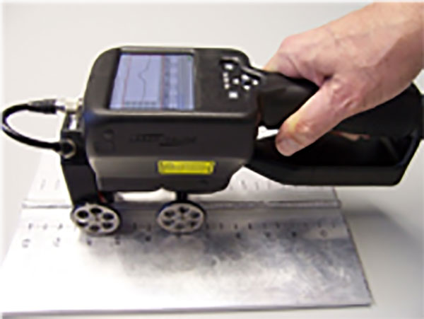
HS702 OR HS703 DSP SENSORS WITH RED OR BLUE LASER SINGLE STRIPE TECHNOLOGY
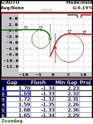
Depending on the diameter of the fastener and the resolution required, an HS702 sensor with either a 1.2" or 1.9" field-of-view is recommended. This DSP sensor displays the profile of the fastener head in real-time on the LCD so that the operator can make sure that the sensor is positioned correctly over the fastener. Measurements are automatic. The operator positions the laser stripe over the fastener and releases the trigger. The edges of the fastener are identified, and the height and/or depth are calculated for both the fastener's left edge and right edge relative to a surface line-fit.
-
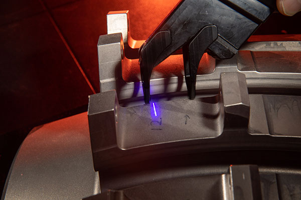
HS742 with Blue Laser Technology
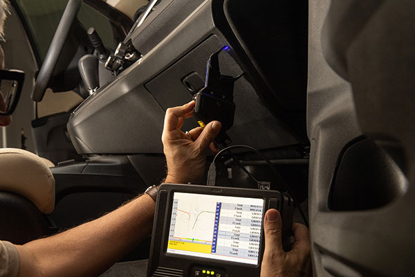
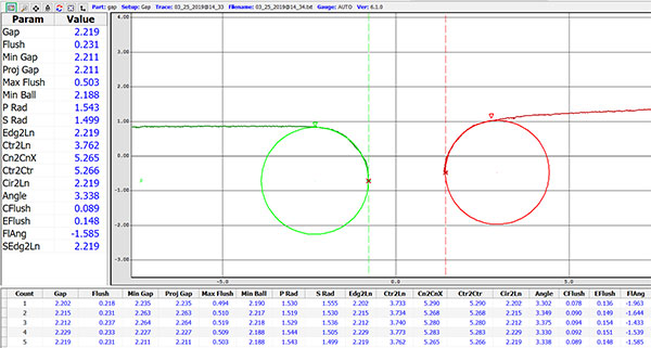
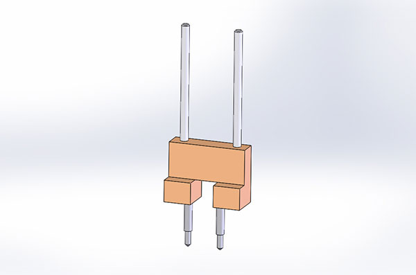
The HS742 DSP sensor is a 3D laser profiler housed in a totally self-contained, portable, handheld package. Expanding on the unique capabilities of the LaserGauge® line of DSP sensors, the HS742 utilizes a laser stripe grid with cutting edge optics and is specifically designed for inspecting and measuring fastener flushness, countersink alignment and dielectric fill height. Surface maps are displayed in real-time on the color LCD, and measurements are extracted and simultaneously written to the data table.
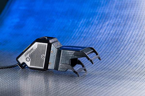
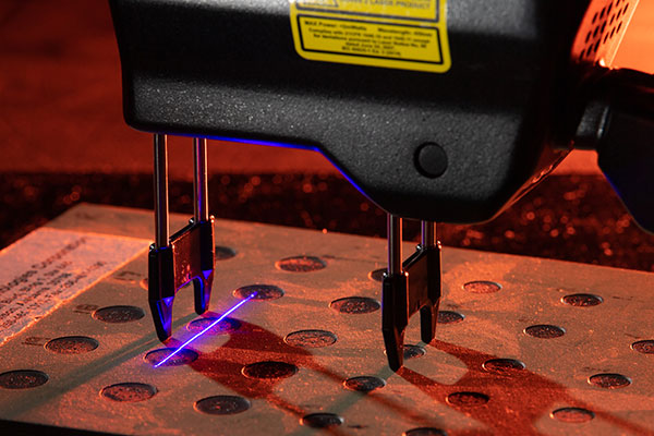
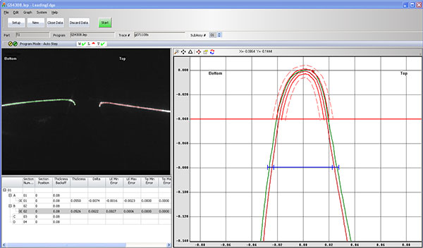
Leading Edge Profile (Bench Top & Handheld)
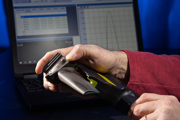
The leading edge of a vane or blade used in aircraft or power system engines must maintain its designed contour within an acceptable range for safe and efficient operation of the engine. Measurements that are critical include the edge radius and the width or thickness of the blade at varying distances away from the edge.
Previously, the only reliable method of inspecting the blade was to use a coordinate measurement machine (CMM). However, this process is very time-consuming and requires each part to be transported to a central location for inspection.
The leading edge inspection algorithm utilizes engineering data to configure a template and match the part to the template at multiple locations. The leading edge is accurately scanned to ± 0.0005” and compared to the template to determine if the contour falls within the acceptable range. All out-of-spec conditions are noted graphically and numerically to the display.
-
Download Application Datasheets
-
Download How-To Guides
Recommended Sensors
-
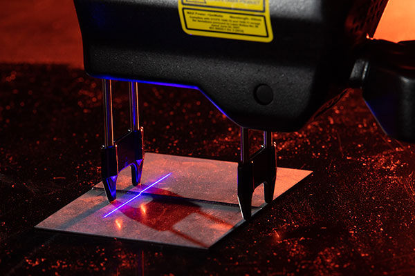
HS730LE 2D SENSOR
The HS730LE sensor has a 0.250" setback range for medium size blades. “Setback” is the distance from the tip of the blade to the furthest point on each side that can be scanned. Anything beyond this is unseen by the sensor. -
HS733LE 2D SENSOR
The HS733LE sensor has a 0.150" setback for smaller blades. -
RS730LE 2D SENSOR
The RS730LE sensor has a 0.375” setback for most larger blades. This system is a bench top sensor can be used at a fixed location, such as a polishing station, or moved from part to part. The sensor has an air fitting on the rear panel to provide a positive purge air flow to help eliminate dust.
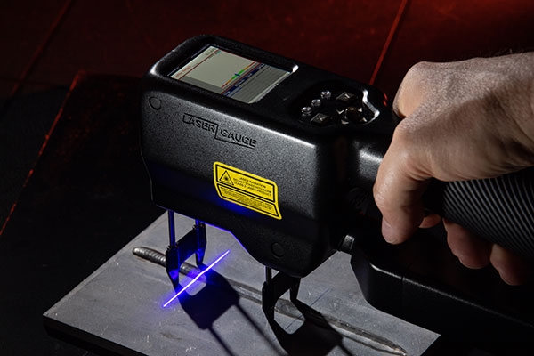
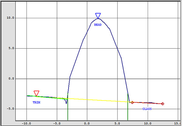
Welds
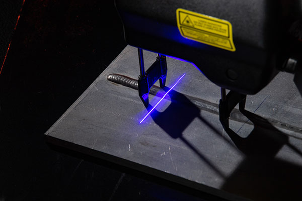

Potential weaknesses in a weld can be revealed in the evaluation of its surface characteristics. The height, width and area of a butt weld are factors in its strength. Also, the fit-up and angle of the panels welded together have a bearing on the integrity of the weld.
Inspection of welds on space vehicles during production and after repair is mandatory. Ultrasonic techniques are used to locate subsurface cracks in the welds; however, the surface features must be inspected using other methods. Operators are able to visually isolate areas of concern on the weld, but they are unable to measure the features with mechanical tools accurately or repeatably.
Tolerances for weld width, height and surface area are expressed in thousandths of an inch. If the weld bead is below the adjacent panel surfaces, it is said to be concave, and the concavity must be measured. The fit of the panels before welding, meaning whether there is difference in the surface heights of the panels and whether the panels are at an angle to each other, also determines the integrity of the weld and must be inspected.
Download Application Datasheet
Recommended Sensors
-
HS702 SENSORS WITH RED OR BLUE LASER SINGLE STRIPE TECHNOLOGY
The HS702 model with a 1.2" or 1.9" FOV could be used. All measurements are automatic. The operator positions the laser stripe over the weld and releases the trigger. The edges of the weld are found based on the edge tolerance selected, and all of the parameters are calculated: weld bead convexity (height), concavity, width, panel mismatch, peaking (panel angle) and weld area. -
TS800 USB SENSOR WITH RED OR BLUE LASER SINGLE STRIPE TECHNOLOGY
A sensor that has a field-of-view that is two to three times the nominal width of the weld bead is recommended. For welds other than very small laser-welds, a TS800 sensor with a 0.50", 1.0" or 2.0" FOV would work best. -
OPTIONAL LG5000 OR LG7000 CONTROLLER
Provides the graphical feedback necessary to allow the operator to position the laser stripe at scores of points along the length of the weld and to view the profile as the measurements are being made.
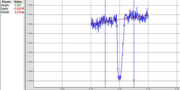
Pitting & Corrosion

Pitting on a jet engine turbine blade requires repair once it exceeds a depth threshold. If the pitting is too severe, the blade cannot be repaired and has to be scrapped. Identifying blades that are eligible for repair saves significant costs for the airlines. Attempts have been made to visually inspect the blades and determine the depth by comparing the pitting coloration to examples or templates. Visual measurements are not always repeatable because of the different individual capabilities of the inspectors. Optical comparators have also been used, but these machines lack the portability desired.
The depth of pitting must be measured and documented to qualify a blade for repair. Thresholds for repair and scrap are in the thousandths of an inch, so the measurement instrument must achieve this resolution.
The measurement of corrosion presents a similar problem to pitting. The severity or depth of corrosion on critical parts such as gears must be measured to determine if repair or replacement is warranted.
Download Application Datasheet
Recommended Sensors
-
TS800 USB SENSOR WITH RED OR BLUE LASER SINGLE STRIPE TECHNOLOGY
A TS800 sensor with a 0.50" field-of-view is used to make the measurements. The sensor has a depth resolution of ±0.0005-inches enabling it to measure the pitting with the accuracy required. Measurements are automatic. The operator positions the laser stripe over the pit and releases the trigger. The edges of the pit are found based on a selected tolerance and the greatest depth of the pit (Min), any material that has been pushed up above the parent surface (Max) and the width (Width) of the pit is calculated and displayed in the data table. -
OPTIONAL LG5000 OR LG7000 CONTROLLER
Real-time plots of the corrosion are displayed on the LG5000 or LG7000 controller as the operator takes the scan. This allows the operator to view the surface as the laser stripe is being moved over the region of interest.
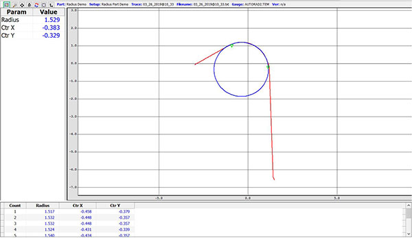
Radius, Break Edge, Chamfers

Download Application Datasheet
Recommended Sensors
-
TS800 USB SENSOR WITH RED OR BLUE LASER SINGLE STRIPE TECHNOLOGY
The TS800 sensor provides feedback to the operator for positioning the sensor. The sensor uses a high-resolution imager and is available in a 0.50", 1.0" and 2.0" field-of-view. Measurements are automatic. The operator positions the laser stripe over the radius, moves the sensor based on feedback and then releases the trigger. The profile of the radius is shown in real time on the computer monitor or controller screen. All measurement values are automatically saved to a data file and the profiles for each measurement can also be saved automatically. -
OPTIONAL LG5000 OR LG7000 CONTROLLER
Allows the operator to view the profile of the feature while taking the measurement and ensure that the sensor is focused on the correct location when the part has several radius or contour lines.
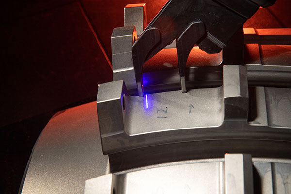
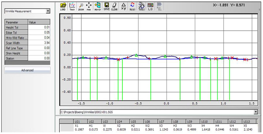
Surface Roughness / Wrinkles
Surface roughness, texture or wrinkles plays an important role in determining how a real object will interact with its environment. Rough surfaces usually wear more quickly and have higher friction coefficients than smooth surfaces. Wrinkles or texture may affect matchup on mating components. Similarly, roughness may promote adhesion and is desirable in some instances if controllable.
Roughness can be measured manually by a visual comparison vs. a known surface roughness or a physical inspection using touch, or a 'scribe' method. Data recording and repeatability between inspectors or shops are often challenges in this scenario. The measurements must provide height and depth of the largest peak and valley, relative to a reference line
Download Application Datasheet
Recommended Sensors
-
TS800 USB SENSOR WITH RED OR BLUE LASER SINGLE STRIPE TECHNOLOGY
Depending on the amplitude and frequency of the texture, a TS800 sensor with either a 0.50 or a 1.0" field-of-view paired with an LG5000 controller is recommended. The TS800 can also be used with a Windows based tablet or laptop running LGCommander. This DSP sensor displays the profile in real-time on the LCD or computer screen so that the operator can make sure that the sensor is positioned correctly. The algorithm automatically measures the height and width of wrinkles relative to a reference line. Returned values give the height of the wrinkle relative to the reference line; the width of the wrinkle and the starting location of the wrinkle, relative to the left endpoint of the scan. Measurements are automatic. The operator positions the laser stripe over feature of interest and releases the trigger. A reference line is calculated, and height and width values are extracted relative to it. -
OPTIONAL LG5000 OR LG7000 CONTROLLER
Allows the operator to view the data table and scanned profiles are stored directly on the controller or computer for review or archiving. No need to manually transfer.